

When all the planning had been completed and a detailed Templot plan had been printed, trackwork construction could begin.
Plain track was built in situ on the layout, pointwork was built in the comfort of member’s homes.
Bank Foot Pointwork
This pointwork was built by Dave Furmage using plastic sleepers from C & L , pandrol clips from Peco and code 82 rail from Intercity Models.
The sleepers were glued in place on the plan using a Pritt stick. The pandrol clips were then threaded on to the rail and then glued to the plastic sleepers using a liquid glue, using gauges and rollers to make sure all the rail stayed in gauge with the correct spacing to check rails.
The frog is a superbly detailed item from the Proto:87 Stores and the fishplates are cosmetic plastic items.
Once the point work was complete, the paper Templot plan was removed and the assembley glued to the cork trackbed.


Regent Centre and Run Round Pointwork
This pointwork was built by Lee Davies using components from the EM Gauge Society. The sleepers were again glued in place on the plan using a Pritt stick. The rail was soldered to the copper clad sleepers – EM Society gauges and rollers were used to make sure all the rail stayed in gauge with the correct spacing to check rails. The Peco pandrol clips were carefully cut in two and then each half glued to each side of the rail on each sleeper.
Once the point work was complete, the paper Templot plan was removed and the assembley glued to the cork trackbed.


Factory Pointwork
This pointwork was built by Trevor Smith using components from the EM Gauge Society. A home made jig for sleeper spacing was purchased on EBay. The bullhead rail was soldered to the copper clad sleepers and cosmetic chairs added with superglue.
On reflection, a better method would have been to use plastic sleepers so that the rail could be raised by a couple of millimetres from the sleeper, leading to a more accurate representation of bullhead points.
Sprung Point
At a club Open Day we experienced a problem that needed a creative solution. With only one operator, it was very difficult to run Metros off the traverser to Bank Foot and stop in the correct position in the station. If the operator worked from the Bank Foot end, no problem with accurate station stops, but the operator then had to walk to the other end of the layout to set the traverser for each metro movement, leaving a layout with time gaps between movements – not an ideal scenario for an exhibition layout.
Solution?
A sprung point. This point uses traditional copperclad soldered construction but the point blade tie bar is attached to a spring so that it remains in the “straight ahead” position. The spring is positioned and adjusted so that the weight of the Metro car can push the point blades across when the Metro enters from the diverging route. A single operator can now run an intensive service from the Bank Foot end without having to align the traverser for each movement.
Plain Track
Trackwork in the factory siding is SMP.
The concrete sleepered track is made using Exactocale FastTrack flexible track bases. The sleeper spacing is not correct for our track and so the webbing was cut and the sleepers slide on to code 82 nickel silver rail. This sub assembley was then laid in place and starting at one end the sleepers were spaced and glued using a 9mm wedge of plasticard to ensure correct spacing – a very tedious task!
The track is glued on to a cork base with a sliver of foam under the outer ends of the sleepers to create about a millimetre of cant on the curved track. The rail is joined with nickel silver fishplates soldered in place to ensure electrical continuity
At baseboard ends, the track was held in place with baseboard track end protectors from C & L Finescale.


The right hand board has the baseboard end track protectors soldered to the rail and then screwed into the baseboard ends.


 Cant!
Cant!

The viewing side of the rails were handpainted with a brown acrylic paint – another task requiring a great deal of patience! The excess paint on the surface of each rail was burnished off with a track cleaning rubber.
Ballasting
A layer of fine sand (play pit sand from Argos) is carefully spread in the areas to be ballasted, extending about 5 millimetres beyond the edge of the ballast.
Woodlands Scenics Medium Buff Ballast was then carefully spread with a teaspoon between the sleepers, tamped in place with the spoon and then tidied with a flat artists brush. With the ballast in place and a “cess” of fine sand, Johnson’s Klear floor polish tinted with Indian Ink was carefully drizzled on with an eye dropper. The Indian Ink darkens the sand, but has litte effect on the ballast.
On the main line, additional ballast was added to the outer edge of the sleepers to represent the extra ballast added to real track on the outer edge of curved track – presumably to aid stability.
In the loco run round, additional ballast was added to the centre line of the track to represent untamped ballast


A brief shaft of evening sunlight through a clubroom window highlights the track.
Trackwork Detail
A site visit was made to the Metro system and photographs taken of the various detail elements. We made simple representations of the details we photographed from plasticard and wire.

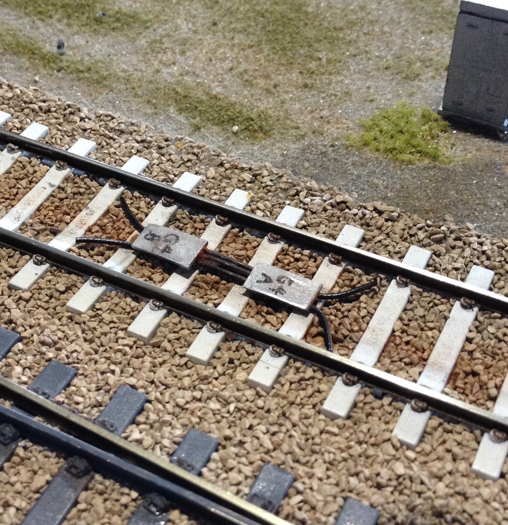
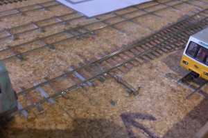
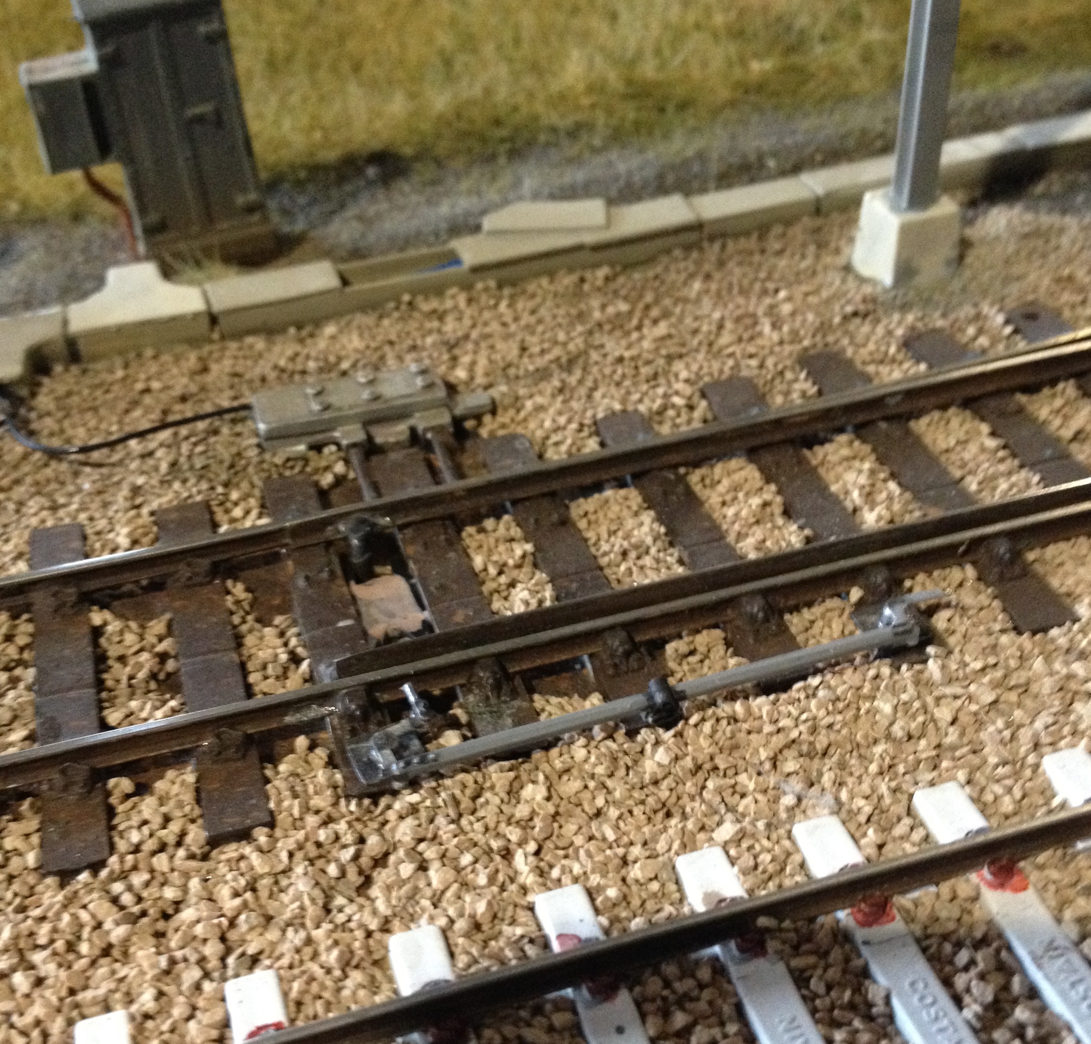
These are Impedance Bonds. They are designed to allow traction return current to bypass track circuit insulation joints. They allow the traction current to flow freely while providing operation and isolation of adjacent track circuits. The handwritten numbers refer to the appropriate track circuits for identification purposes. They are usually located just behind signals where there are track circuit breaks and insulated fishplates.
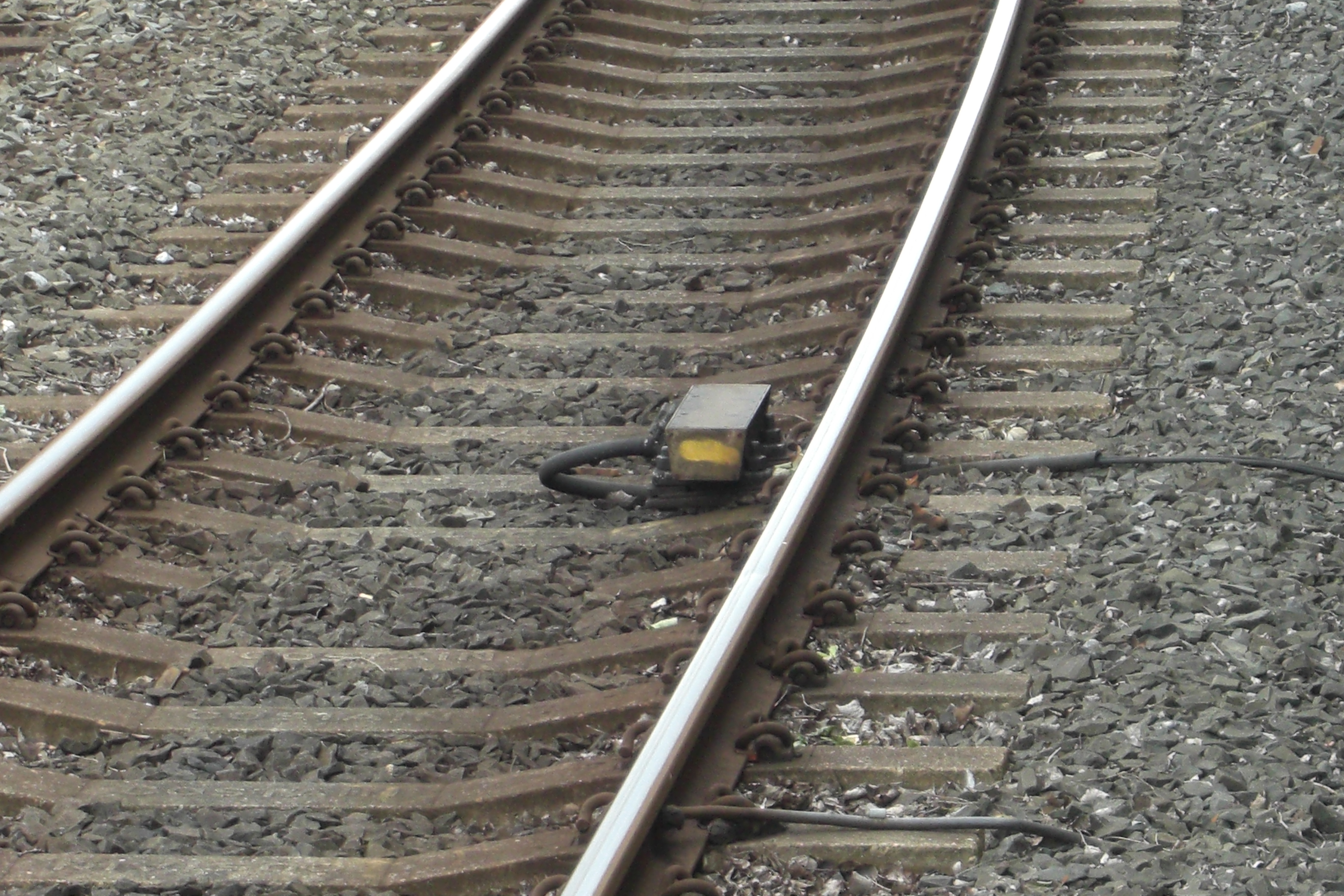

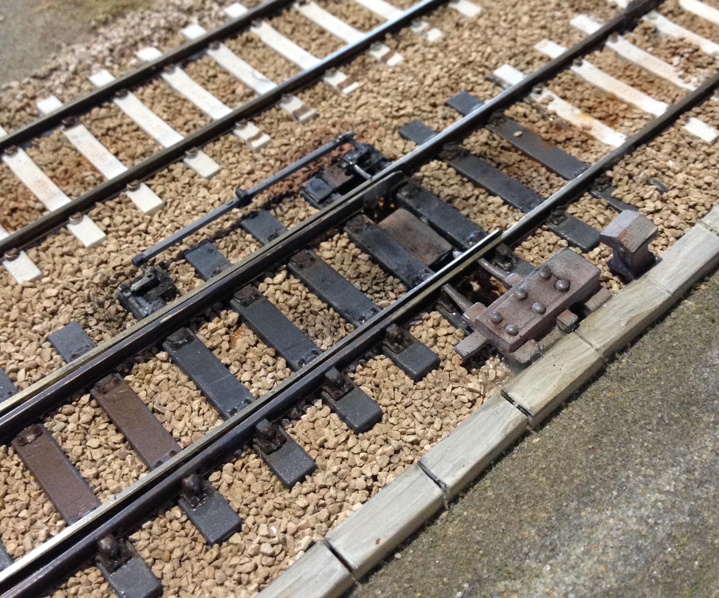
These are Indusi Loops. They are of German manufacture and provide automatic train protection. They are found opposite signals and work with a receiver on the Metro cars – if a Metro car passes a red signal the train brakes are automatically applied, a yellow signal must be passed at a defined speed to prevent the automatic application of brakes.
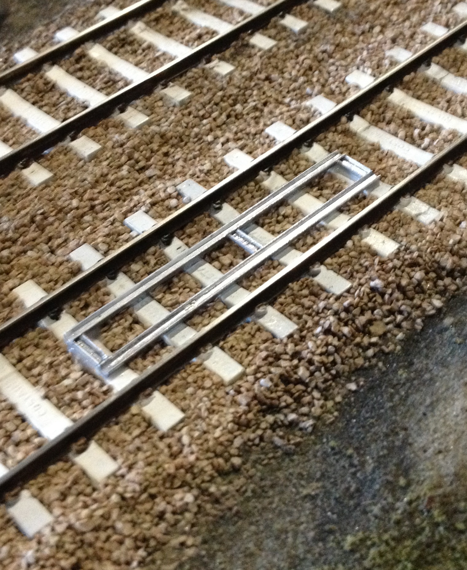
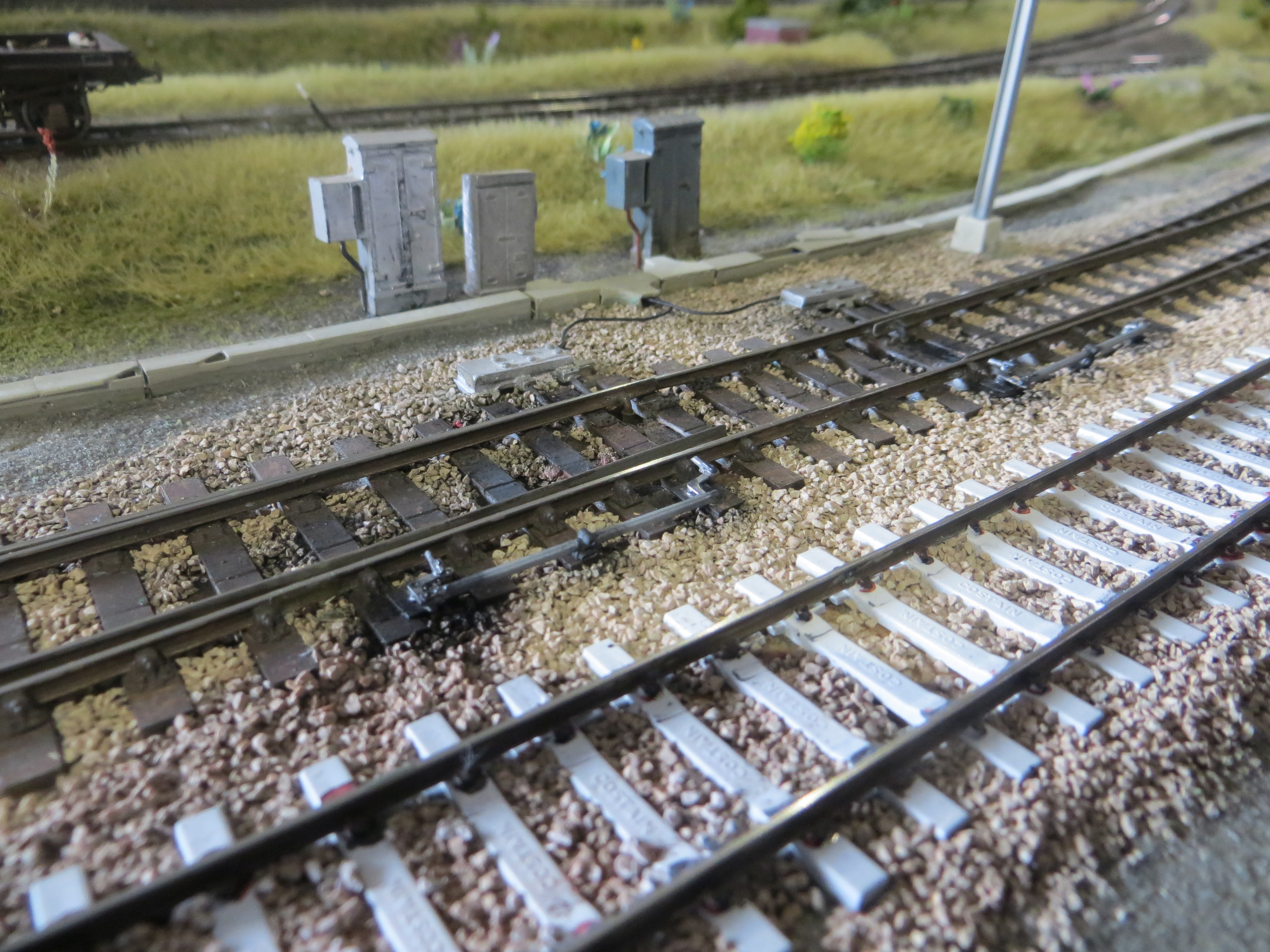
These assemblies provide information about the location of the Metros and are used to implement route setting and in cab information. Nick Smith, a retired Westinghouse Signal Engineer, provided us with the information about these track details.
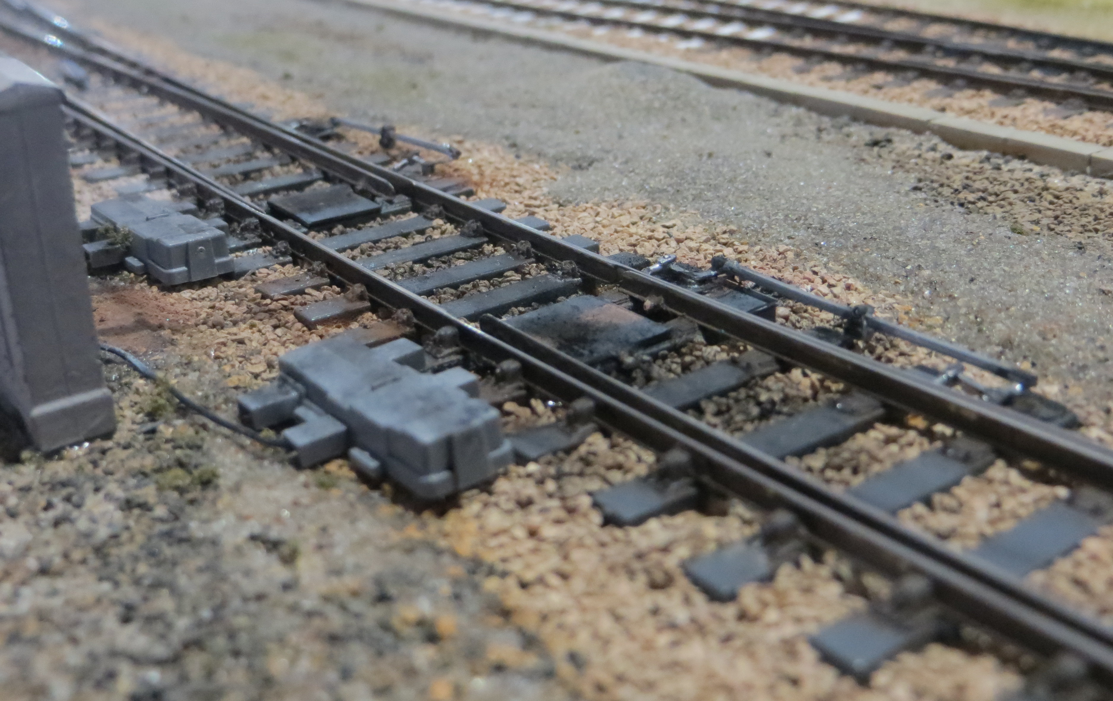
The points were detailed with point rodding, a mixture of the Wills point rodding kit and some Brassmaster etched brass crank.s When complete, the area around the points was weathered with black pastel powder – created by rubbing a black artists pastel on sandpaper to create a powder.

Very impressive, and a good writeup,